
Guides Earthworks takeoff How-to
How to calibrate a PDF site plan so the quantities are right
Scale bars lie. How to calibrate a PDF or scanned plan, check it with a second dimension, and spot the reissue that was printed at the wrong size.
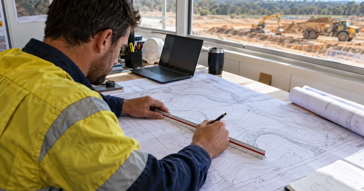
A PDF has no idea how big it is. It is a picture, and the only thing that turns it into a measurable drawing is you telling it what one known distance really is. Get that wrong and every number downstream is wrong by the same proportion — quietly, consistently, and with no error message.
This takes about ninety seconds. It is the highest-value ninety seconds in the whole takeoff.
Step 1 — Find a distance you can trust
In order of preference:
- A written dimension on the drawing. A lot boundary marked 32.50, a building setback, a road reserve width. This is the best source because it is the engineer's own number.
- A scale bar. Fine, but only as good as the print, and the ends are often fuzzy on a scan.
- A grid. Survey grids are drawn at known intervals and span the sheet, which averages out small clicking errors.
Avoid anything short. Clicking a 2-metre dimension puts every pixel of your aim into the answer; clicking a 40-metre one dilutes it by twenty.
Step 2 — Click the two ends and type the real length
Add the plan as a layer, choose the calibration tool, click the two ends of your chosen distance, and type what it actually is. The whole layer is now in metres.
Zoom in before you click. At a comfortable reading zoom, a careless click is a couple of pixels; on a 1:500 sheet that is most of a metre.
Step 3 — Check it with a second dimension somewhere else
This is the step everyone skips and the one that pays.
Measure a different known dimension, ideally at the other end of the sheet. If it reads what the drawing says it should, you are calibrated. If it is out, do not adjust and move on — something is wrong and you want to know what.
Step 4 — Work out why it disagrees
Three common causes, in order of how often we see them:
The PDF was printed to a different size. Somebody exported an A1 drawing to A3 for emailing. Everything on the sheet is uniformly smaller, including the scale bar, so the scale bar still looks right while the stated ratio is now a lie. Your measured dimension is the truth here.
It is a reissue that was not re-plotted properly. Revision C was regenerated at a different sheet size from revision B. Check the title block. If your two measurements disagree consistently by the same ratio, this is usually why.
The sheet is genuinely not to scale. Some details are drawn indicatively and labelled NTS. You cannot take off from these — no calibration makes an indicative sketch measurable. Get the proper sheet.
If the two measurements disagree by different amounts in different places, the PDF is a photograph or a skewed scan of a paper drawing. Distortion is not uniform and no single calibration will fix it. Ask for a native PDF or the CAD file.
Step 5 — Prefer the CAD file when it exists
DXF and DWG carry their own units, so a CAD layer arrives already scaled and there is nothing to calibrate. If units are missing from the file, the layer is flagged as uncalibrated so you know to set it yourself rather than quietly trusting a guess.
If the engineer sent both, add the CAD as a second layer and use the PDF for the annotations. It removes this whole step, and it often carries the levels too. See DWG and DXF takeoff in the browser.
Why does scale calibration matter so much?
Scale error does not stay the size you made it. A 2 per cent error on your calibration is 2 per cent on every length, about 4 per cent on every area, and roughly 4 per cent on volumes where the depth comes from levels rather than the plan.
On a $400,000 earthworks job, 4 per cent is $16,000. It is usually more than the margin, and it arrived from two careless clicks in the first minute.
Measure twice. It is the cheapest insurance in estimating.
Next
Once the sheet is calibrated, the rest of the takeoff follows: boundary, existing levels, design levels, a 3D check. That is walked through end to end in Cut and fill from a PDF plan in about ten minutes. You can calibrate and mark up plans on the free plan at takeoff.sitesai.net.
Questions people ask
The plan says 1:200 — can I just enter that?
Only if you are certain the PDF has not been resized, and you usually are not. Entering a stated ratio trusts the print; measuring a known dimension trusts the drawing. Measure.
What if there is no dimension and no scale bar?
Use something you can verify on site or in another document — a lot boundary on the title, a standard road reserve width, a building footprint from the architectural set. Failing that, ask for the CAD file.
Does calibration affect volumes or only lengths?
Both, and volumes worse. Length scales with the error, area with its square, and volume with its square as well, since depths come from levels rather than the plan. A 2 per cent scale error is about 4 per cent on your dirt.
Do CAD files need calibrating?
Usually not. DXF and DWG carry their own units, so the layer is scaled on import. If units are missing the layer is flagged as uncalibrated, and you set the scale the same way as a PDF.
Try it on your next plan set — free.
Sign in with Google or Microsoft, add a PDF or DWG/DXF, and see cut and fill in minutes. Pro is US$39 per user per month, the AI plan has a free 14-day trial; cancel any time. What SitesAI Estimate does.